From: Genome Reference Consortium

The NCBI Handbook [Internet]. 2nd edition.
Bethesda (MD): National Center for Biotechnology Information (US); 2013-.
NCBI Bookshelf. A service of the National Library of Medicine, National Institutes of Health.
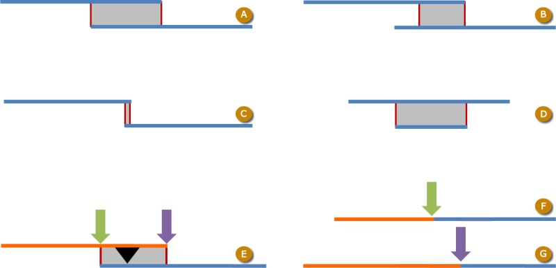
Schematic of component overlaps and switch points. Blue and orange bars represent components, gray boxes indicate aligned regions, and switch points located at either extent of each alignment are indicated by thin red lines. A: Full dovetail alignment. This is the type of alignment that is expected for adjacent TPF components. B: Half-dovetail alignment, in which the end of one of the components does not align. While such alignments may be indicative of two components that do not belong together, this situation can also occur if the components contain untrimmed vector sequence or overlap in a repetitive sequence of variable length. C: Short/blunt overlap (< 50 bp). These alignments always require external evidence in the form of a join certificate. D: Contained alignment, in which one component’s sequence is contained in the other. This situation is generally observed when the shorter component is being used to correct an error in the longer component. E: Default switch point position (purple arrow) between two assembly components. Because of an indel in the alignment (black triangle), moving the switch point (green arrow) may change the resulting sequence. F: Sequence constructed from alternate switch point (green arrow) in panel E. G: Sequence constructed from default switch point (purple arrow) in panel E.
From: Genome Reference Consortium
NCBI Bookshelf. A service of the National Library of Medicine, National Institutes of Health.